ad2

ad1

Selasa, 18 September 2012

Test set-up model WISE-8

Test set-up model WISE-8

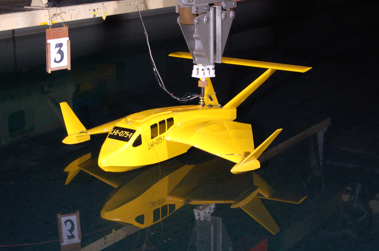
Test set-up for Wise in the Towing Tank models can be seen in Figure 1.


 Figure 1. Model Test Set-Up.

Figure 2. Position gauge pressure transducers on the model WISE
 

Before the implementation of the model testing, performed heavy arrangements and emphasis WISE prototype model of the size-8 with reference to the equation 'Froude Law'. Frame hook is used to adjust the height and angle of landing model, in which the frame is mounted and attached to the trains pull (towing carriage). Pressure transducer measuring instruments (Ø = 1.3 cm diameter) installed at some point (area) below the surface of the model have been determined.
Configuration pressure transducer mounted below the surface of the model can be seen in Figure 3, the pressure transducer position in the model is denoted as follows:
- F1: in front midship area
- F4: the midship area
- F6: on rear midship area
- F7: the pontoon section Starboard
- F8.: The portside pontoon section.


Senin, 13 Agustus 2012

TEST RESULTS LANDING Tests

TEST RESULTS LANDING Tests
 
The results of the analysis and evaluation of the impact load water at a height of 11 cm and 22 cm from the surface of the water presented in the form of the curve (see Figure 4-7) and Table 5-6. Measurement data presented is the model scale value.

Table 1. Water impact force on the model to the height of 11 cm


No
Landing Angle (deg)
Model
Speed
(m/s)
Water Impact Forces of Model
F-1
(gr/cm2)
F-4
(gr/cm2)
F-6
(gr/cm2)
F-7
(gr/cm2)
F-8
(gr/cm2)
1
0
0
14.80
8.54
3.33
4.41
5.48

2
0
3.89
33.74
37.25
20.85
20.85
33.75
3

4.86
71.38
63.01
65.42
60.77
74.24
4

5.83
32.91
46.43
74.46
74.46
56.65
5

6.89
15.65
16.40
27.69
27.69
19.23

6
5
3.89
 42.82
7.22
11.61
11.61
21.75
7

4.86
88.41
90.56
46.42
88.96
85.29
8

5.83
64.88
-
36.75
77.74
57.52
9

6.89
68.75
80.67
44.28
-
91.63
 

Table 2. Water impact force on the model to the height of 22 cm

No
Landing Angle
 (deg)
Model
Speed
(m/s)
Water Impact Forces of Model
F-1
(gr/cm2)
F-4
(gr/cm2)
F-6
(gr/cm2)
F-7
(gr/cm2)
F-8
(gr/cm2)
1
0
0
15.28
7.15
16.43
3.79
50.05

2
0
3.89
35.93
43.56
9.50
29.93
10.82
3

4.86
29.97
32.18
90.64
18.56
7.33
4

5.83
24.10
11.44
17.52
14.54
12.29
5

6.89
21.98
28.97
18.42
32.11
28.75

6
5
3.89
14.74
7.35
11.71
12.24
14.85
7

4.86
6.92
7.73
31.91
24.76
8.11
8

5.83
17.74
65.02
10.02
27.35
43.45
9

6.89
29.00
22.78
11.64
-
-
From the table above, it is shown that the maximum pressure that occurs at 90.56 gr/cm2 diarea midship (see table 1) and 90.64 rear midship gr/cm2 diarea (see table 2).

  In the table also shows the difference adana pressure (but not significant) in some testing and it disebakan due to the influence of surface water waves perturbed towing tank at the time of measurement.
Thus, the data above can be used as a reference in the calculation of material life time and the strength of the material used in the prototype design WISE-8.